Our Fireplace

We have been working, off and on, on our fireplace. We plan to install a woodburner boiler halfway along the north wing, in the lounge/dining room and backing on to the kitchen/family room. This is to supplement/complement the air-sourced heat pump (underfloor heating) and the PV panels (hot water). The boiler should be capable of heating both hot water and the underfloor heating. In the grand scheme of things we would expect to use only the heat pump and PV panels over the summer months and to use the woodburner occasionally over the spring and autumn and heavily over the winter months, with the heat pump filling in the gaps e.g. overnight. For the first year or two, we have a large supply of old roof timbers to feed it.

We installed an air supply under the floor slab using 110mm soil pipe, this will feed at least a 14KW stove. We have our eyes on an Arada stove that puts most heat into water and much less into the room, in which case we should be able to get up to 12KW into hot water, the same output as the heat pump.

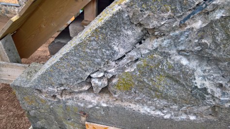
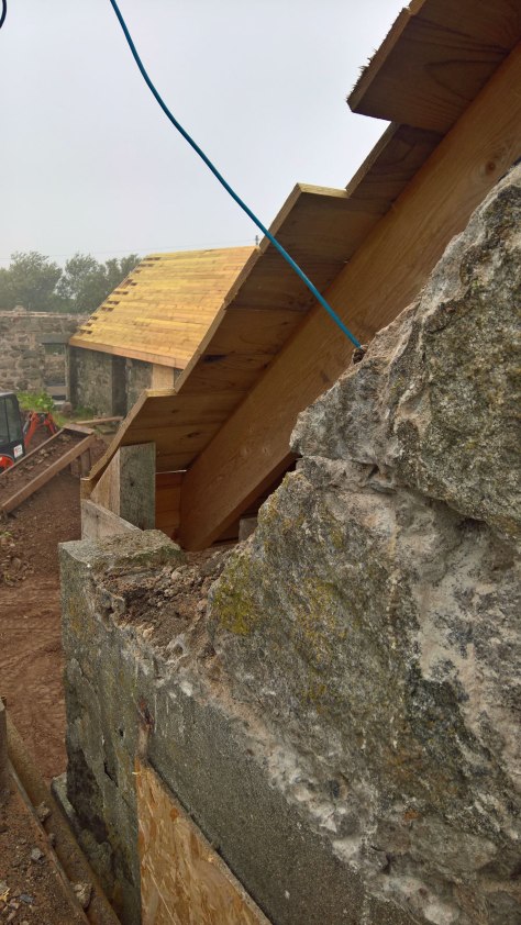
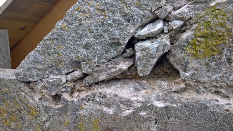
We planned to build the fireplace from granite, using the large lintel we retrieved from the west wall of the west wing, over the large opening that we have blocked in. It was 2.6m long and needed George’s big digger to lift off and transport. We just managed to lever it into the north wing using the mini digger and used rollers and levers to get it roughly where we needed it. It has been increasingly in our way ever since and now that we want to insulate the east and north wing floors, we need to at least create the fireplace foundation and do something about the lintel.

Agreeing the general size, shape and appearance of the fireplace was not easy. We looked at what other people had done in similar circumstances and we did not like most of them. We want to make a statement, but not to oppress. We want to use as much of the lintel as possible, but need good open access along the north wing. Using the full 2.6m of lintel would leave us only 1.5m of spare width. So we decided on the fireplace being no more than 1.9m wide, giving a 1.2m passageway one side, in line with the openings between the east and west wings, and room for storage the other side. The fireplace will be off-centre, by around 30cm, which should not be a problem. We want to see granite at the front and inside the fireplace, but not above the lintel or around the sides and back. So we will back the granite with mortar/concrete that will allow us to dot & dab plasterboard right up to the edges of the stonework. Above lintel height we will use concrete blockwork then just a timber framework above that to ceiling height. That will give us a good thermal mass around the stove, but let us run double-walled stovepipe up through the roof.

With a eye to the building standards, we settled on the hearth being 1300mm wide and 900mm deep, allowing the side walls to be 300mm thick and the back to be 280mm. The hearth will project forwards 230mm, so that the stove can be at the front of the fireplace.

We used sarking board to make the formwork and cast 150mm of concrete. This will be 15mm below the screed and will allow us a choice over the height of the hearth, either flush with the finished floor, or raised above. I built ducting from concrete block and slate, at the bottom, to allow the air supply to be used from whichever side of the fireplace we wanted.

We let the concrete harden for a week before building upwards. We used some of our best Peterhead (red) granite quoin stones at the front, with the good faces at the front and inside of the fireplace. We built three courses, to get around 1050mm above the foundation. We used shuttering to back the quoins with concrete, to stiffen it enough to support the lintel. For the rest of the fireplace we picked over our granite rubble to find particularly flat faced boulders that were skinny enough to keep within our designed thicknesses. We did not complete the back of the fireplace at this point, because the pressure was on getting the lintel cut to size and hoisted up onto the quoins.

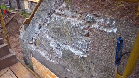
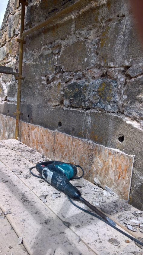
We trimmed the lintel to length by drilling seven 18mm holes across the width at each end and using the feathers and tare set to split the ends off. Then it was using the angle grinder to cut the ends square and the bush hammer to soften the edges and roughen the surface.

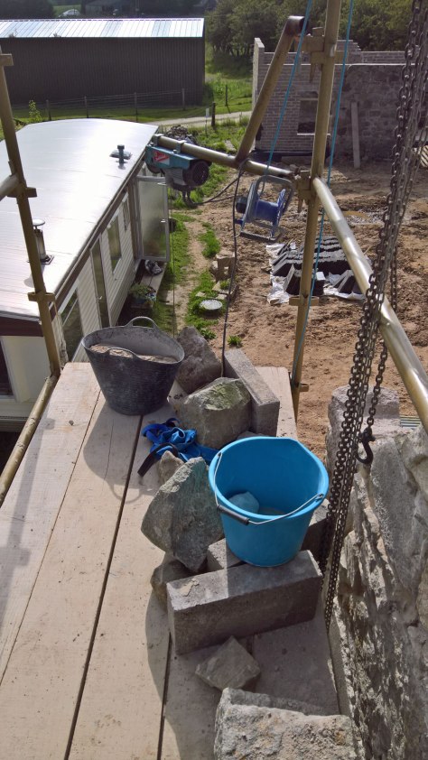
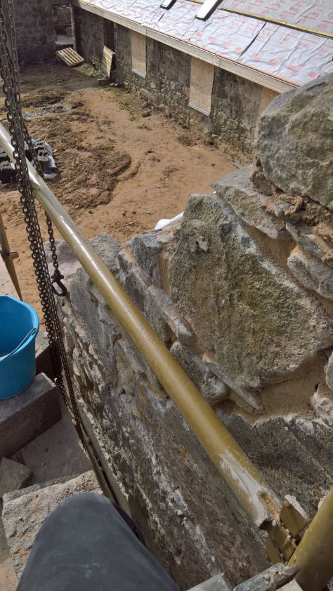
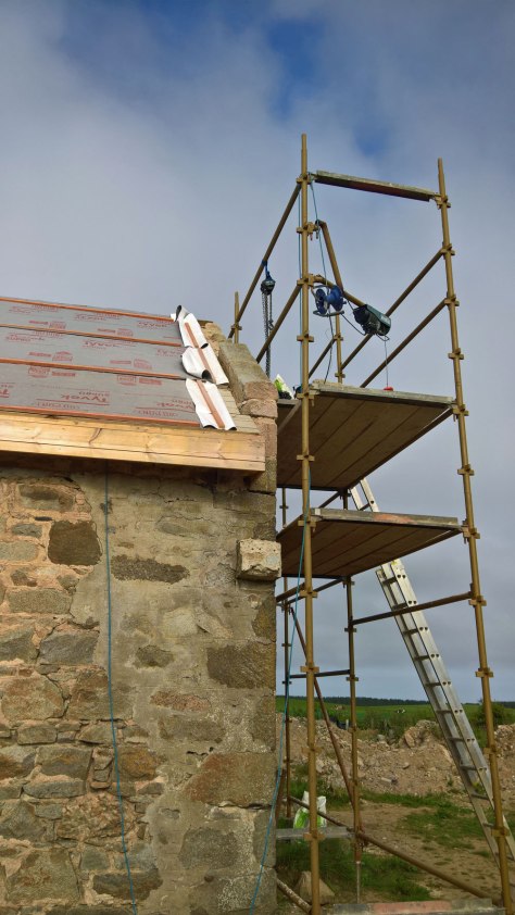
Thus we were left with a 2m length of granite that was around 350mm tall and 280mm wide. This worked out to around 500kg and our chain hoist was only rated to 500kg – it seemed a close-run thing whether it would survive the lift. We built a bay of scaffolding over the fireplace, with three scaffold boards on edge above the lifting point to support the hoist. We manoeuvred the lintel using our stone trolley and rollers half onto the foundation, the idea being that we could lift the lintel and, once at height, simply rotate it round to rest on the quoins. We could then shuffle it precisely into place. And this is exactly what happened. The chain hoist survived, although we built columns on concrete blocks underneath the ends of the lintel as it went up, just in case. We got the lintel lined up with the quoins, horizontal across the opening and with a vertical face. Then we removed the concrete blocks and scaffolding and were able to press on with floor insulation. We will not be tripping over the lintel any longer!

The north-east gable end

On finishing work on the south gable end of the east wing, we moved straight on to the north end. The objective was the same, to raise the wall to meet the new roofline, to allow us to slate the roof and flash it into the coping stones on the parapet. 

When we bought the property in 2014, the north gable end was in a bad way.

The retaining stones for the coping had fallen off or been removed, along with half the coping stones. We removed the survivors because there was not really anything to stop them sliding off onto us.  We removed the top few courses of stone above the upper floor window so we could replace the wooden inner lintel with concrete ones. In 2018 we repaired the stonework, installing a matching pair of retaining stones that we had acquired from the old farmhouse next door. At the same time we put the backing blockwork in above the old roofline, to fill the gap to the current trusses and sarking. 

So we had less to do: Lay stone in front of the concrete blockwork, then install the coping stones. We used the same arrangement of scaffolding, with a high platform across the middle of the wall and a lower platform that we built first one side, then moved to the other side as we completed the work. The stonework was quite quick, two and a half days work in total to build up both sides to the height of the window lintel and to lay courses above the window up to the apex. I was mindful of the problems i had with the copings on the south end and generally finished the stonework a few cm below the sarking. I only had to trim one stone, to fit a particularly deep coping stone. I did, however have to use copings from our south-west gable end to replace the missing ones, we will have a problem to sort out when we restart work on the west wing. I used both the starting stones (with the shallow end that rests in the hollow on the retaining stones) and at least one other on each side. Both sides took a days work to complete. 

So including prep time and scraping the mortar back ready for final pointing, we got the whole thing done in six long days. We were quite happy to see the end of it and move onto other jobs. Ric is back in a few days and we need to prepare for slating and floor screeds. 

The last sill – For our big window

We worked on the sill for our big window in the south wall of the east wing. Two reasons. Firstly it is the last complete opening still missing its sill. Secondly, we cannot finish insulating the east wing until it is done. It is around 3m high and wide and we had left it with the foundation blockwork built up to finished floor level, with tanking membrane laid up the back edge. We decided to leave it as is and to build the sill on top. This will lift the window proper above floor level, reducing the possibility of anyone accidentally running anything directly into the window frame or glazing. In fact, we do not have a sill that is 3m long, we will prepare two of our 1.6m lintels and join them in the middle.

The blockwork at the base is 100mm. This a bit skinny and we wanted to widen it nearer to 200mm. We dug out the ground immediately in front to foundation level and laid concrete above it, to level it up to 200mm below ground. We mortared a second course of blocks in front, to ground level, then faced above it with a thin layer of granite and finally a course of lime mortar above to create a 10-degree slope outwards. Once it had gone off enough, 48 hours or so, we lapped tanking membrane up and over the mortar.

We found two lintels that matched in height and width and processed them as we had our other sills. Propping the sills at a 10-degree angle, we sliced the fronts vertically off with the angle grinder and bush-hammered the faces. Then we cut the undersides at 90 degrees to the front and sliced drip grooves into them. Finally it was a case of slicing them to length, notching either side of the window opening so the ends of the sills slotted into them. We did a dry run installing them, to check the alignment and that they fitted. They lined up well, with a gap of a couple of mm between them. We fitted eight of our chunky steel angle brackets to the blockwork underneath, stuck strips of foam on the base to spread the weight of the sills and put them in place permanently. We used squirty foam underneath the sills then screwed the sills to the angle brackets. And that was it, though we will need to fill the gap between sills, possibly with epoxy resin mixed with stone dust.

Raising the south-east gable wall

We have been pottering on for weeks now, raising the south gable end on our east wing, to match the raised roofline. Whilst I knew what needed to be done – remove the copings, lay a retaining stone at the correct height for putting the coping back on, adding stonework above the existing, replacing the copings and, for good measure, picking out the cement morter some criminal had
slathered over the stonework – It took me ages to get my head around how to fit it all together. As always, once I had finished, I knew what I needed to do and how to approach it.

About the gable wall
We had raised the wallheads by around 440mm, with four courses of concrete blocks, at the same time the architect had specified the roof to slope at 42 degrees, not 45 degrees. So there was a biggish space to fill in at the eaves and this diminishes at the ridge to around 300mm.

The gable wall is different from the others in that it had been rebuilt at some point with the large opening, which had been designed to have a sliding door across it. The right-hand wall had been built on beyond the building line, to allow the door to slide out the way. So the left hand side had the copings running down to a normal retaining stone, but the right hand side simply ran down onto a concrete slab lying on top of the wall extension. I planned to keep this arrangement, so only needed one retaining stone.

So I gingerly levered the coping stones off the wall with the help of the chain hoist, as I worked up first one side, then the other. I took them down to ground level to clean off the cement mortar they had been pointed with. On reflection, I think the cement mortar is good for pointing the copings, it is much harder (weatherproof), obviously, than lime, but it also blends well with the grey granite. I used the angle grinder to cut a 5mm wide and 25mm deep groove down the inside edge of each coping stone, 30mm from the top edge, to tuck lead flashing into.

Early work
The entire wall had been pointed up with large quantities of extremely tough cement mortar. This gave the impression that the stonework was all large, regular blocks of roughly dressed granite, not the field stone rubble used in the rest of the structure. This was only partly the case, my investigations showed that they had used smaller stones to get courses up to level, but they had worked hard to disguise it. For example, there was not a proper retaining stone at the west side, the bottom end of the first coping was lodged into the gap between two stones.

Having started removing the cement render on the north wall of the north wing, I went straight to the Makita rotary hammer to break up the mortar. It did indeed, but was a slow and dirty job that swallowed us several working days I between the other jobs.

Retaining stone
I had a rather rough and worn retaining stone from the old farmhouse. I spent a half day building up the stonework to support it, with a lot of uncertainty about the exact height it needed to go. In the end I cut a template of the stone out of OSB and stuck batten legs on it that I could stand on the original level. I needed to ensure that the perpendicular distance between the sarking and the top lip of the stone was around 150mm. I ended up happy that it was probably about right. I screwed two lengths of strapping between the retaining stone and a large block of the original wall, just in case the new lime mortar had not gone off enough to support the copings.

Backing concrete blockwork
The next step was easy – building the backing concrete blockwork up from the old roof level to the new. I cut corners off the blocks so that they fitted snugly right under the sarking boards.it took 19 courses to reach the blockwork Ric had put in to support the ridgeboard and jack rafters over our gallery area.

Stonework
Building the stonework in front of the blocks was less satisfactory. I aimed to use large square blocks to carry on the style of the gable, but found out that there was not really the room to get more than one block in, with small stones to fill in the slopes. It looked quite messy, but there was not a lot of choice. I did not want to spend days cutting and splitting oversized stones to exact size or breaking out existing stonework to create more room.

Replacing the copings
I left putting the coping stones back on until I had finished the stonework, In retrospect this was not a good idea: I had built up some of the stones so that they were in the way and I had to rebuild several bits to get them out of the way. This added days to the work, waiting for the lime mortar to go off again. Had I fixed the first one back early on, I would have adjusted the stonework to suit.

The lowest coping had a different profile to the higher ones, with a flatter lower surface at the bottom end to rest in the corresponding dish in the retaining stone. My first placing showed that the retaining stone was 20-30mm too high, giving a perpendicular distance between sarking and coping of around 180mm. I took the angle grinder to the bearing point on the retaining stone and cut out about 20mm. This time the perpendicular distance was 160mm and this happened to be what it was at the top end of the stone, so I went with it. I spent some 30 minutes tweaking the position so that the slope was exactly that of the sarking, that the stone was exactly horizontal across the width and that it went exactly up the outside edge of the stonework. I filled the gaps under the coping stone with mortar and with small stones on the outside face. I left the stone to start to go off, then started the second one. I had wrongly supposed that this would slide down onto the first one and apply pressure to it, in fact the bearing points on the wall took the strain and I was able to leave a maximum 10mm gap between stones. I used one small stone and pieces of slate at the bottom to get the coping aligned exactly with the top of the first stone and two at the top to get the top exactly level, at the same slope as the roof and first coping and exactly lined up with the edge of the stonework. And so I worked up to the apex of the gable wall, leaving a respectable line of parapet.

The other half of the gable wall
With the left-hand slope sorted, we moved one bay of scaffolding to the other side and I started on the right-hand wall. It was more of the same except that I did not need to put in a retaining stone for the coping. Instead I took the angle grinder to the concrete slab across the top of the extended piece of wall and created a shallow depression to lodge the first coping into This did lengthen the coping by another stone, I had to pillage one from one of the other sets. This is a problem, made worse because the other end of the east wing had lost the bottom coping stones before we bought the property. We have a couple of stones that could be fashioned into coping, it would be quite a bit of work. We have a couple of spare lengths of pink coping, but it would probably not be a good look mixing colours.

Fascia panels finished – for the north and east wings

We finished making the remaining powder-coated fascia panels we need for the north and east wings, 9 for the north side of the north wing, 6 for the east side of the east wing and a short one for the stub of fascia for the west side of the east wing, on the north end. It went smoothly enough, with fewer re-coatings needed as we improved our handling of the un-cooked panels – around three days work to cut and fold the panels, clean them, spray them with primer, cook them, spray them with top coat, cook them, make the joiners from aluminium 2” x 1/7” bar, coat them, install them and install the eaves trays above them. The joiners covered much better than with the first batch, I needed to recoat only two of them. Again, it really improved the appearance of the fascia.

Woodworking machine

We now own a combination woodworking machine that has a circular saw, a planer/thickness planer and a spindle moulder. Most of what we need to make our own windows. Ric was going to ship his Kity combination woodworking machine up here to work on windows and doors, but he worked out that it would be no more expensive to buy our own. So we kept an eye on eBay. A Kity machine duly appeared but we missed out on it through incompetence on my part – I was working on the south east gable wall and forgot to bid. A few days later, a Robland X26 machine appeared, I strategically bid a significantly higher amount than the current bid and I ended up the owner for £640.

I hired a van and did a weekend dash down to Leicestershire to collect it. It was in the corner of a large workshop, everything that should run did, although the spindle moulder did take a few goes before the brake disengaged. Then it a case of snipping off the power cable. The bloke selling was in his seventies and the machine was a bit of a beast to move, so we struggled a bit. It had wheels and a sort of jack to lift it off the ground so we heaved and hoed until we got it to the back of the van. We enlisted a third body to get it in. We tipped it onto the side, leaned it against the back of the van and with a bit of a struggle lifted/slid it in upside down. I got all the attachments and a set of moulder heads.

I drove on down to Leamington to stay the night at my daughter’s house, collected a desk that went in the front of the van, then set off a bit after 5am, getting back to the steading mid-afternoon. I was faced with getting the machine out of the van and into the north wing on my own. I used the chain hoist strapped to a strategic big bag of washed gravel to haul the machine out of the van almost to tipping point. I lowered/dropped the end down onto two scaffold boards then used the chain hoist again to pivot it back clear of the van, which I was able to pull forwards out of the way. I laid a trackway of 18mm OSB sheets from there to the front door opening and, with the mini castors I had used to move furniture out of the house in Kessingland under one side of the machine, it was remarkably easy to shuffle it along right up to the front door, do a right angle turn and slide it down onto the concrete slab. It worked well and the van was completely undamaged, I dropped it off the next morning without issue.

Blocking off the open end to the north wing

We have temporarily blocked off the opening between north and west wings. It will not get sorted out properly until we get the west wing roof on, which is not happening anytime soon. We built the structural timberwork across the gap a week or so ago, I screwed on four sheets of 11mm OSB, this almost completely covered the full width. I cut the corners off two sheets at 45 degrees, so that they could be fixed side-by=side over the end-most truss, right up to the top of the rafters. I fixed lengths of batten to the first one and used these as stilts, to lift the sheet into place. It left me free to get up a ladder and screw the panel into the rafter and the collar. I unscrewed the battens and used them for the second sheet. They were slightly wonky, this was because when I battened the roof membrane to the rafters, that too was wonky. The corners I cut off the first two sheets fitted either side of the two I had already fixed. So two full sheets of OSB covered the whole truss down towards the wallhead. This left a vertical and horizontal gap between studwork and rafter. I used batten to construct a lean-to roof which I covered with sarking boards, then membrane, stapled at top and bottom to the OSB. Not pretty, but it should keep the worst of the rain and wind at bay.

More on fascia panels

With the aluminium folder, the powder sprayer and the oven all working, we pressed ahead with creating all the remaining dozen panels we needed for the north and east wings on the courtyard side. We processed them in pairs, more than that and I struggled to lift them in and out of the spray booth without brushing them against me or the spray booth. Indeed the biggest problems throughout were caused by poor handling. Two panels had enough defects that I recoated them, which was OK, but did not produce as even a finish as the first topcoat.

I noticed that the resin primer powder behaved quite differently from the polyester top coat. It was easier and quicker to spray on in even coats and I could cover three panels from one bottle of powder. The top coat took longer to apply, was more liable to blow out of the sprayer unevenly, took a higher airflow setting and used half as much again as the primer – two panels per bottle. I did get better with the spraying, but in fact the process was quite forgiving – it was not difficult to get a good finish. I bothered less about the top section of each panel, which would be under eaves trays and slates, working for best results on the bottom half. With a 90 minute cycle time to clean, spray, load into the oven, cook, cool and remove, we could get 6 panels a day done.

As we got the panels done, we fitted the first six to the fascia boards. We lifted the panels up ladders and seated them over the bottom edge of the fascia, at which point they held themselves on. I used copper 3mm x 30mm nails to fix the top fold to the bottom sarking board, checking that adjacent panels were lined up at the bottom.

We intentionally left 1cm gaps between panels because we intended to make brackets to cover the ends. We wanted the brackets to be distinctively different from the panels, so the joins did not look as though had simply been done badly. I went back to Aalco and collected three 6-metre strips on 2” x 1/8” bar. For some odd reason aluminium bar is still sold in imperial units. The bar was surprisingly heavy, whippy and much stronger that I would have expected. I did not take a saw with me and could not fold the bar, so I pushed one end up one side of the inside of the car, pulled the other end round and pushed it up the other side. When we got home, I took them out and they sprang back to being flat straight strips.

I cut a 40cm length off and used the vice on our big workbench to hold one end whilst I tried to fold it to match the profile of the panels. It failed because I found it very difficult to fold, being so springy. When it did fold, it failed with distinctive failure lines. I gave up for a day or so and looked for (and failed to find) alternatives. So I tried again, this time going for a smooth ‘u’ shape at the bottom. After a couple of goes, I got a wide enough fold that would fit reasonably snugly over the bottom folds on the fascia panels. I measured the top 45-degree fold against the panels as I made the brackets and did these as tight as I could even though they tended to show some signs of fracturing – these would not show under the eaves trays. The brackets were for some reason much harder to coat evenly compared to the panels, possibly because the fractured areas did not charge well from the spray gun. I got them all primed, but had to give most of them two top coats. However, I got all the brackets in in one batch. The brackets were quick to install, with a single nail through a 3.5mm hole I had drilled through the top. The effect was exactly what we had hoped for and it made the fascia panels look very classy.

I pretty much straight away put the eaves protector trays on above them. The fit mostly over the sarking and under the membrane, with the short side hanging down over top tops of the panels, to carry water safely from the membrane over the edge of the roof. Whilst it did conceal the tops of the panels, the effect was really quite neat and very effective. Rain water subsequently ran onto the trays and dripped from the edges of the trays, a few mm proud of the panels. All much better that painted fascia board.